|
|
|
The TRE/TR Evaluation Kit provides an easy connection to any of Javad GNSS OEM boards. It is designed for use in laboratories and allows:
The kit consists of:
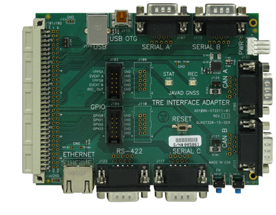
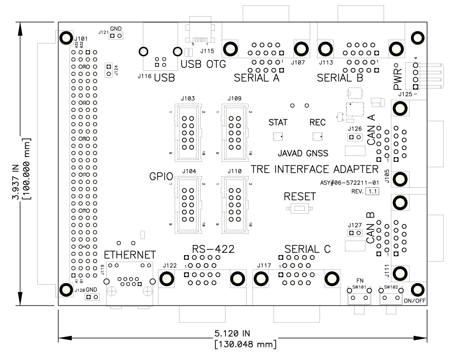
The TRE Interface Adapter is supposed to be used with TRE series of OEM boards. The TRE series currently consists of the TRE-G2T, TRE-G3T, TRE-G3TAJ, Duo-G2, Duo-G2D and Quattro-G3D receivers. The TRE Interface Adapter brings all the interface signals combined at 64-pin DIN41612 Euro connector out to the standard connectors for each interface type. Below is a short description of all the connectors (both standard and non-standard) located on the TRE Interface Adapter.
The J101 is a 64-pin DIN41612 Euro connector to be plugged into the interface connector of the tested OEM board.
The J116 "USB" connector is a standard USB type B receptacle. A standard USB cable (not included in the kit) can be used to connect to a TRE-XXX receiver via J116.
The J107 "SERIAL A", J113 "SERIAL B" and J117 "SERIAL C" are standard DB-9 Male connectors for three RS232 ports. Table 1 shows pin out description for the three connectors. A standard null-modem cable (not included in the kit) can be used to connect a PC to a TRE-XXX receiver via one of these connectors.
Table 1. Pin out for J107 "SERIAL A", J113 "SERIAL B" and J117 "SERIAL C"| Pin # | Signal Name | Direction | Description |
|---|---|---|---|
| 1 | - | - | |
| 2 | RXD | In | Receive Data |
| 3 | TXD | Out | Transmit Data |
| 4 | - | - | |
| 5 | GND | - | Ground |
| 6 | - | - | |
| 7 | RTS | Out | Request to Send |
| 8 | CTS | In | Clear to Send |
| 9 | - | - |
The J125 "PWR" is a 4-pin header for input power. The 4-Pin Header to Banana Plugs Power Cable #14-508021-01 is supposed to be used to power a TRE-XXX receiver via this connector. Reverse Polarity Protection is provided for input power voltage at this connector.
The J105 "CAN A" and J111 "CAN B" are DB-9 Male connectors for two CAN interfaces. Table 2 shows their pin out description. Two 2-pin headers control optional 120-Ohm termination resistors for the two CAN buses: J126 for CAN A and J127 for CAN B. To terminate CAN A with a 120 Ohm resistor at J105, install a jumper at J126. To terminate CAN B with a 120 Ohm resistor at J111, install a jumper at J127. The factory default is no termination (no jumpers).
Table 2. Pin out for J105 "CAN A" and J111 "CAN B"| Pin # | Signal Name | Direction | Description |
|---|---|---|---|
| 1 | - | - | |
| 2 | CANL | In/Out | CAN Low |
| 3 | GND | - | Ground |
| 4 | - | - | |
| 5 | - | - | |
| 6 | - | - | |
| 7 | CANH | In/Out | CAN High |
| 8 | - | - | |
| 9 | - | - |
The J122 "RS-422" is a DB-9 Male connector for RS-422 interface. Table 3 shows its pin out description.
Table 3. Pin out for J122 "RS-422"| Pin # | Signal Name | Direction | Description |
|---|---|---|---|
| 1 | GND | - | Ground |
| 2 | - | - | |
| 3 | GND | - | Ground |
| 4 | TXD+ | Out | Transmit A (Non-Inverted) |
| 5 | TXD- | Out | Transmit B (Inverted) |
| 6 | - | - | |
| 7 | - | - | |
| 8 | RXD+ | In | Receive A (Non-Inverted) |
| 9 | RXD- | In | Receive B (Inverted) |
The J119 "ETHERNET" is a standard RJ45 Female connector for 10/100BASE-T Ethernet. Table 4 shows its pin out description.
Table 4. Pin out for J119 "ETHERNET"| Pin # | Signal Name | Direction | Description |
|---|---|---|---|
| 1 | LAN_TX+ | Out | Transmit Data+ |
| 2 | LAN_TX- | Out | Transmit Data- |
| 3 | LAN_RX+ | In | Receive Data+ |
| 4 | - | - | |
| 5 | - | - | |
| 6 | - | - | |
| 7 | LAN_RX- | In | Receive Data- |
| 8 | - | - | |
| 9 | - | - |
The J103 is a 2x5 header (Samtec #TST-105-01-G-D-ND) for discrete timing signals. Table 5 shows its pin out description.
Table 5. Pin out for J103| Pin # | Signal Name | Direction | Description |
|---|---|---|---|
| 1 | 1PPSA | Out | 1 Pulse Per Second output A |
| 2 | GND | - | Ground |
| 3 | EVENTA | In | Event imput A |
| 4 | GND | - | Ground |
| 5 | 1PPSB | Out | 1 Pulse Per Second output B |
| 6 | GND | - | Ground |
| 7 | EVENTB | In | Event imput B |
| 8 | GND | - | Ground |
| 9 | IRIG_OUT | Out | IRIG port output line |
| 10 | GND | - | Ground |
The J104 "GPIO" is a 2x5 header (Samtec #TST-105-01-G-D-ND) for configurable GPIO signals. Table 6 shows its pin out description.
Table 6. Pin out for J104 "GPIO"| Pin # | Signal Name | Direction | Description |
|---|---|---|---|
| 1 | GPIO0 | Out | Configurable Logic-Level I/O 0 line |
| 2 | GND | - | Ground |
| 3 | GPIO1 | In | Configurable Logic-Level I/O 1 line |
| 4 | GND | - | Ground |
| 5 | GPIO2 | Out | Configurable Logic-Level I/O 2 line |
| 6 | GND | - | Ground |
| 7 | GPIO3 | In | Configurable Logic-Level I/O 3 line |
| 8 | GND | - | Ground |
| 9 | - | - | |
| 10 | GND | - | Ground |
The TRE Interface Adapter also contains the following controls:
The TR-G3T Cross Adapter is supposed to be used in combination with the TRE Interface Adapter for TR series of OEM boards. The TR series currently consists of the TR-G2, TR-G3, TR-G2T and TR-G3T receivers. The TR-G3T Cross Adapter essentially converts a small 40-pin interface connector of the TR-XXX OEM boards to a standard 64-pin Euro connector of the TRE-XXX OEM boards.
