
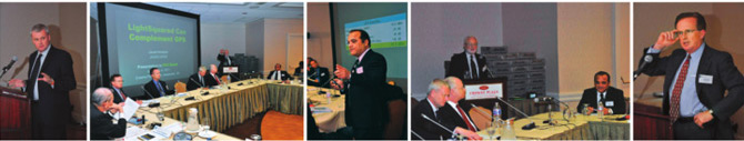
1) At the PNT meeting of November 9, 2011, in Alexandria, Virginia, we showed that LightSquared 10L (Base Station) and 10R (Handset) signals have absolutely no negative effect on GPS. Our solution also improves GPS performance.
2) We covered these topics in private meeting of November 8 and public meeting of November 9. Scientists from NASA, academia, and GPS manufacturers were present.

3) All positioning, navigation and timing devices also need the communication module. In the past 30 years we have perfected the PNT/ GNSS module, but we still suffer from lack of a good communication system.
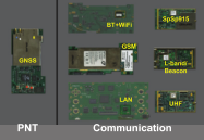
4) On the left is the GNSS/PNT module. The modules on the right are communication modules that we currently use in our GNSS devices. None are reliable, inexpensive and trouble free.

5) LightSquared can solve GNSS communication needs. We presented solution to make GPS compatible with LightSquared 10L and 10R (Handset) signals. We will test against 10H (Base Station High) later.
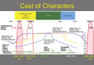
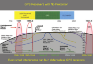
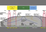
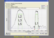
6) LightSquared signals are shown in red and GPS and GLONASS signals in green. The existing filters (purple, yellow, blue) do not provide any “fence” between LightSquared and GPS/ GLONASS.
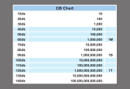
7) This dB chart shows relations between normal numbers and dB numbers. We use dB numbers to present the effect of our filter solution in the following slides.
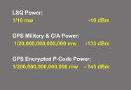
8) We assumed -10 dBm (0.1 milliwatt) for LightSquared 10L and 10R signals. This is higher than the maximum power that might ever be seen even next to a LightSquared transmitting tower.
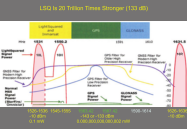
9) Even though GPS encrypted P-codes are 20 trillion times weaker than LightSquared signals, our solution provides for LightSquared signals to have no negative effect on GPS.
10) The shaded area is our old filter which provided no fence against LightSquared or any other signal near GPS. All LightSquared signals are well within the fence! This is typical of all manufacturers GPS filters.
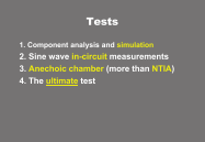
11) We verified our innovative filter with four different tests. These tests cover everything from details of circuit design to the ultimate performance demonstrations like multipath mitigation features.
12) Component Analysis test is to examine the electronic components to see if they can help to build the fence. This is like a cursor examination of the body of a patient.
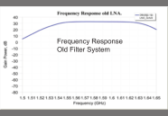
13) This is the shape of our old filter which shows the gate is wide open and cannot protect.
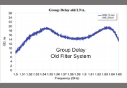
14) Group delay feature is not a critical item any more. This is just to show the group delay shape of our old filter system.
15) Sine wave in-circuit test is injecting signals and see the circuit performance in different sections. This is like attaching the EKG probes to the body of a person to examine the heart function in different parts of the body.
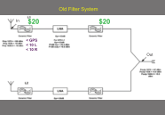
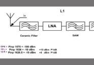
16) Probe readings of the GPS, 10L and 10R signals through our old filter system. The filter had 2 ceramic filters, $20 each.
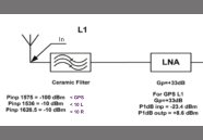
17) Zoom-in of the input part of the previous slide. Sine waves with the specified powers at GPS, 10L and 10R frequencies are injected to the input.
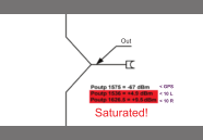
18) Zoom-in of the output part of the previous slide. Filter was not able to suppress 10L and 10R signals and the system is saturated. No need to do any further test. First two tests showed that our old filter system des not work.

19) Next we focused on explaining our solution and proving its performance with four different tests.
20) This is what the shape of the old filter. No fence! We need to design a filter which does not let 10L and 10 R in.
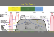
21) This is the shape of our new filter. It provides complete protection against 10L and 10R. We will show the results of four tests on this new filter in the following slides.
22) First is the component analysis test of the new filter system.
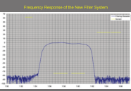
23) This is the shape of the new filter as seen by the Agilent signal analyzer. It looks good and promising to provide good protection. This by itself is not enough. See the result of the actual tests too.
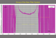
24) We solved the effect of group delay variations two years ago when we invented a technique to address its effect on GLONASS FDMA. Similarly, we can com-pensate for the effects of large Doppler shifts on LEO satellites.
25) Next, we showed the sine-wave in-circuit test for the new filter. This is what we called “EKG” test.
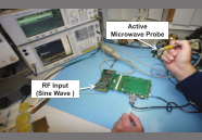
26) Test set up for the in-circuit test. The EKG-type probe is shown in the hand of our engineer.

27) We put the sine wave closest to the GPS signals both on the 10L and on the 10R side as shown by “^^^^^” symbols.
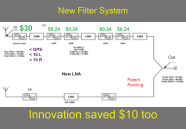
28) We replaced two ceramic filters ($40) with one ($30) and added four SAW filters ($1). We saved $10. This slide shows readings of sine wave powers of GPS, 10L and 10R frequencies as they pass through the new filter system.
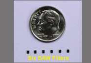
29) The relative size of SAW filters compared with a dime (US coin).
30) 1-dB compression point of the filter for 10L and 10R frequencies are +10 and +8 dBm, respectively. This means our filter can tolerate signals much stronger than 10L and 10R (20 dB and 18dB more!).
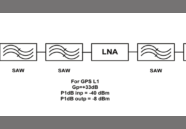
31) Zoom-in of the middle section of the new filter. 1-dB compression point for the GPS L1 is -40dBm at the input and -8dBm at the output. These do not concern 10L and 10R and shows the tolerance for in-band signals.
32) Zoom-in of the end of the filter system. GPS signal after passing this filter is 1dB higher than 10L and 3dB higher than 10R.
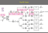
33) After filter system, signals go through the RF chain of the GPS receiver. This is the readings of GPS, 10L and 10R signals as they pass through 7 modules of the RF system. We will focus on the GPS L1 band.
34) Zoom-in of the input section of the RF chain. The input powers shown, as provided by the filter system discussed earlier.
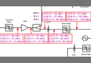
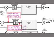
35) Zoom-in on the mid section of the RF chain showing strength of sine wave test signals. RF ceramic filter, LNA, splitter, attenuator, and SAW filter blocks are shown here.
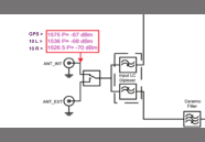
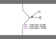
36) Zoom-in of the last section of the RF chain. Multiplexer and IF SAW filter blocks are shown here. 10L and 10R signals are completely gone (relative to the GPS signal). We summarize results in the next slide.
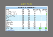
37) The right two columns show the relative strength of GPS compared to 10L and 10R as passes through different modules. 10L and 10R have completely disappeared at the end of our RF chain.
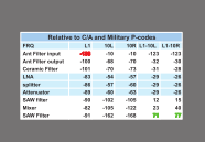
38) Relative strength of 10L and 10R compared to the pure GPS signals. Civilian users do not have access to the un-encrypted P-code and have to use its encrypted version which is much less effective.
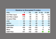
39) Relative strength of 10L and 10R compared to encrypted P-code signals. Our filter makes even this weak GPS singal more than million times stronger than 10L and 10R. Filter does the job.
40) Next we focused on the Anechoic Chamber test of the new filter. This is like the stress test of the heart. Our Anechoic Chamber test is more comprehensive than NTIA tests.
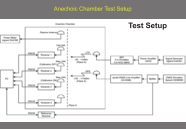
41) GPS, 10L and 10R signals are broadcast inside the sealed chamber and picked up by the GPS receivers under test. The sealed chamber and signal generators provide controlled environment for the test.
42) Signal generators and test equipment are outside the chamber and connected to the units under test inside the anechoic chamber.
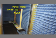
43) Close up of the anechoic chamber and the antennas connected to the GPS receivers. The power meter is a passive antenna that is used to measure the strength of signals near the GPS antennas.
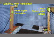
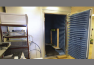
44) Inside the anechoic chamber. Generated signals are broadcast from the left side and picked up by antennas on the right side.
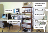
45) Test equipment outside the anechoic chamber. They generate GPS, 10L, and 10R signals and monitor the performance of the GNSS receiver inside the chamber.
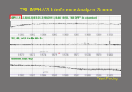
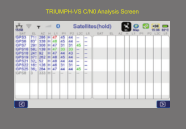
46) Screen of Interferences Analyzer of TRIUMPH-VS. See www.javad.com for detailed description of this subject.
47) Another screen of Interferences Analyzer of TRIUMPH-VS. See www.javad.com for detailed description of this subject.
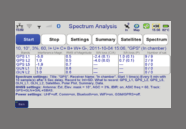
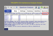
48) Another screen of Interferences Analyzer of TRIUMPH-VS. See www.javad.com for detailed description of this subject.
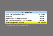
49) Even on the worst case, LightSquared signals have no effect on LEO satellites, which at worst case can see the -20 dB side lobes of the transmitters. The powers seen by LEO satellites are less than -58 dBm.
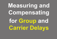
50) Next we discussed our earlier innovation of measuring and compensating for group and carrier delay variations of filter systems which is particularly important for timing applications.
51) We announced this innovation two years ago. This is one of our booth panels at 2009 ION conference.
52) Another screen of Interferences Analyzer of TRIUMPH-VS. See www.javad.com for detailed description of this subject.
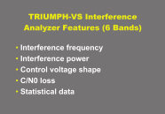
53) Interference Analyzer features of TRIUMPH-VS. See www.javad.com for detailed description of this subject.
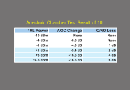
54) Our filter systems can protect against 10L powers even with much higher powers than its authorized power. We stopped the test at +4.5 dBm because our transmitter could not generate higher powers.
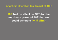
55) Anechoic Chamber test results on 10R. Our filter systems protects against powers much higher than the authorized power of 10L. There is absolutely no negative effect. Our AGC system could not even see any trace of 10R signal.
56) The impact on the accuracy and multipath mitigation capabilities of the new filter system. We call this “the ultimate test” because it can readily show any negative effect on the performance of the filter and the overall system.
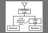
57) Block diagram of the ultimate test. Signal from the same antenna is fed to our conventional receiver on the left and to the new filter system on the right. The comparison of the two provides the ultimate test!
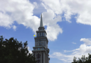
58) Antenna is mounted in the marked location which is subjected to multipath from above and below the antenna.
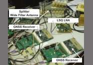
59) Test set up inside the office. Antenna is routed to the left and the right. On the left is the old wide-band antenna. On the right is the new LightSquared compatible new filter system.
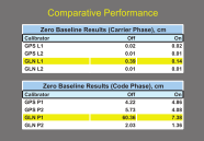
60) The zero-baseline result is 0.2 mm (0.007 inch). The total effect is smaller than the thickness of a business card! On/Off columns show group delay calibration helps GLONASS signals when it is ON. All units are in cm.
61) Next we calculated the effect of 44,000 Light Squared-transmitters on Low Earth Orbit Satellites. NASA was worried about such effects on their LEO satellites.
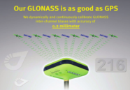
62) Calibrating for GLONASS inter-channel biases is achieved by measuring the group and carrier delay variations.
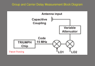
63) Block diagram of measuring group and carrier delay variation invention. We generate GPS and GLONASS like signals, send them up to the antenna, receive them back, and measure their travel times.
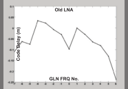
64) Group delay variations of different GLONASS satellites. Each GLONASS satellite is 500KHz away from its neighbor (maximum variation of 5.5 MHz).
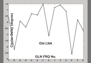
65) Carrier delay variations on different GLONASS satellites. We can use the same technique to compensate for carrier delay variations if Doppler shifts are significant for GPS in LEO satellites.
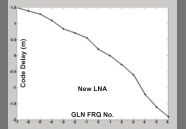
66) GLONASS group delay variations with new filter. We dynamically and continuously measure and compensate for group and carrier delay variations.
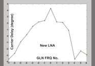
67) GLONASS carrier delay variations with new filter.
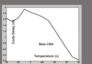
68) Group delays also vary due to temperature. Our group delay compensation technique is very helpful for timing applications too. We can automatically compensate for temperature variations.
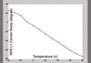
69) Carrier delays also vary due to temperature. Our carrier delay compensation technique is very helpful for timing applications too. We can automatically compensate for temperature variations and provide Pico sends time transfer.
70) This is the manufacturing test sheet that goes with every antenna. At PNT meeting we had 40 LightSquared compatible antenna ready for those who wanted to take and do their own tests.
71) This is the manufacturing test sheet that goes with every antenna. At PNT meeting we had 40 LightSquared compatible antenna ready for those who wanted to take and do their own tests.
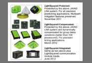
72) Furtheremore by March 2012 we will release products for timing applications and by June 2012, we will introduce products integrated with LightSquared communication modules.