These are ways that we defend against jammers and spoofers and inform users of details.
J-Shield Filter
and Near Band Interference
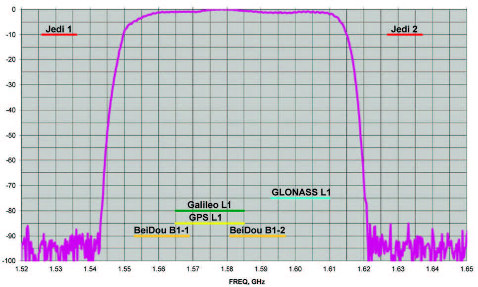
J-Shield is a robust filter in our antennas that blocks out-of-band interference. In particular signals that are near the GNSS bands like the LightSquared signals. The graph on the right shows the protection characteristics of our J-Shield filters. It has a sharp 10dB/KHz skirt which provides up to 100 dB of protection. It makes the precious near band spectrums available for other usages and protects GNSS bands now and in the future.
FIR (Digital Filter)
and In-Band Interference
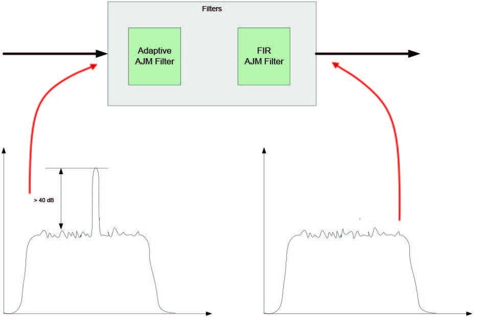
Our In-Band protection digital filter protects against in-band interference like harmonics of TV and radio stations when you get close to them, or against illegitimate in-band transmissions. Our in-band interference protection is based on the 16 adaptive 80th-order filters. AJM-filters can be combined in pairs for complex signal processing. This filter can simultaneously suppress several interference signals.
The 16 FIR AJM-filters can be combined in any number in chain. Each filter is a 255 order FIRfilter. It can be used to suppress the stationary interference signal in programmable (in compare with adaptive AJM-filter) area or for spectrum shaping. To have more suppressing areas or more aggressive suppressing one can combine FIR_AJM serial.
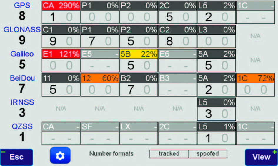
In-Band noise Measurement
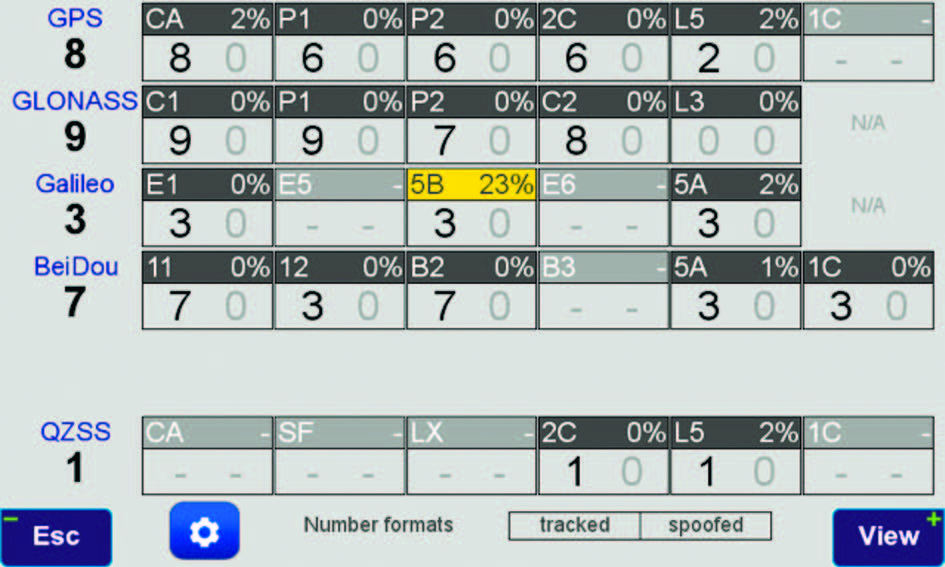
This figure-of-merit number shows the level of interference as percentage of noise above the normal condition. The first row of the first screenshot shows the condition in a clean environment. 8 GPS satellites were visible (according to the almanac). 8 C/A, 6 P1, 6 P2, 6 L2c and 2 L5 GPS signals were tracked. The noise level is 2% on C/A and L5, and 0% on P1,P2,and L2C. The screenshot below that, shows 290% noise in GPS C/A and %121 on Galileo E1. Only one of 8 GPS C/A code and none of 5 Galileo E1 signals were tracked.
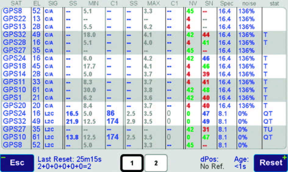
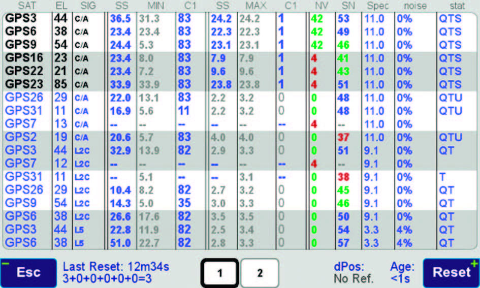
This typical screenshot shows details of each signal. In the last column (T) indicates the signal was tracked by the main channels, (Q) by the Fast Acquisition Channels and (U) signal was used in position calculations. The SN color coded column shows the signal-to-noise ratio of tracked signals. Blue is perfect, green is 3 dB down, and red is 6 or more dB down. Percentage numbers show the percentage of interference above the normal level. We explain other columns later.
No jammer can escape our
figure-of-merit test.

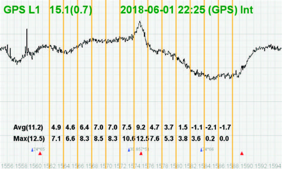
Spectrum Shape
We have a very powerful spectrum analyzer within
our GNSS TRIUMPH chip. Each spectrum shows
the power and the shape of the interfering signals
and jammers. This is more powerful and more efficient
than having a $30,000 commercial spectrum
analyzer to evaluate the environment. The screenshot
on the right shows the shape of the GPS L1
band spectrum when the band is not jammed. The
GPS C/A code peak at the 2-MHz center of the L1
band is visible.
The height of the spectrum is 11.2 dB.
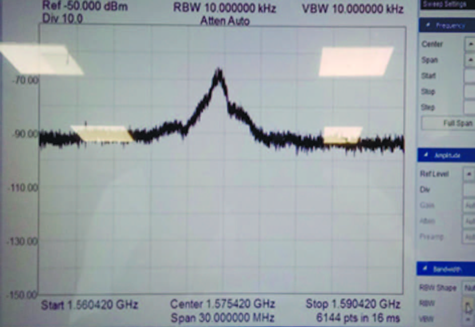
This is an example of GPS L1 spectrum with a commercial $30,000 spectrum analyzer.
Our integrated spectrum analyzer has the advantage that it monitors the spectrum inside the chip where it matters. It has effective bandwidth of 1 KHz.
Our embedded spectrum analyzer also has the advantage that it can be programmed to automatically record the spectrum (and other information) periodically or according to the set conditions, and monitor the environment continuously.
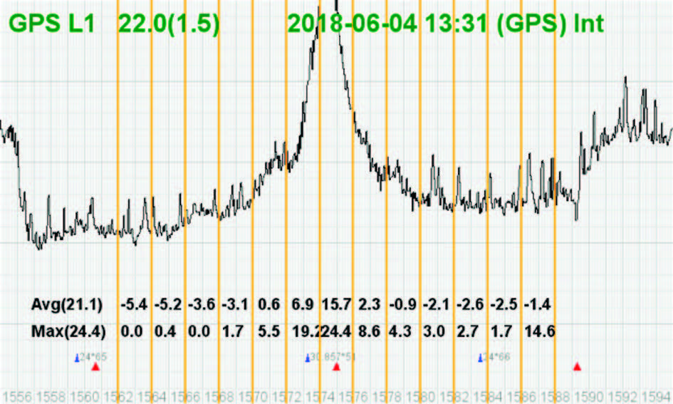
This is the spectrum example of a GPS L1 band when it is jammed. There is a huge peak in the center where the C/A code is. The number on the bottom left is the height of the peak.
The height of the spectrum is 21.1 dB, which compared to the calm 11.2 dB, indicates about 10dB of jammer.
Although we label the bands as three GPS and 3 GLONASS bands, but they represent all bands of all GNSS signals, because bands are shared by all GNSS signals.
AGC
Automatic Gain Control
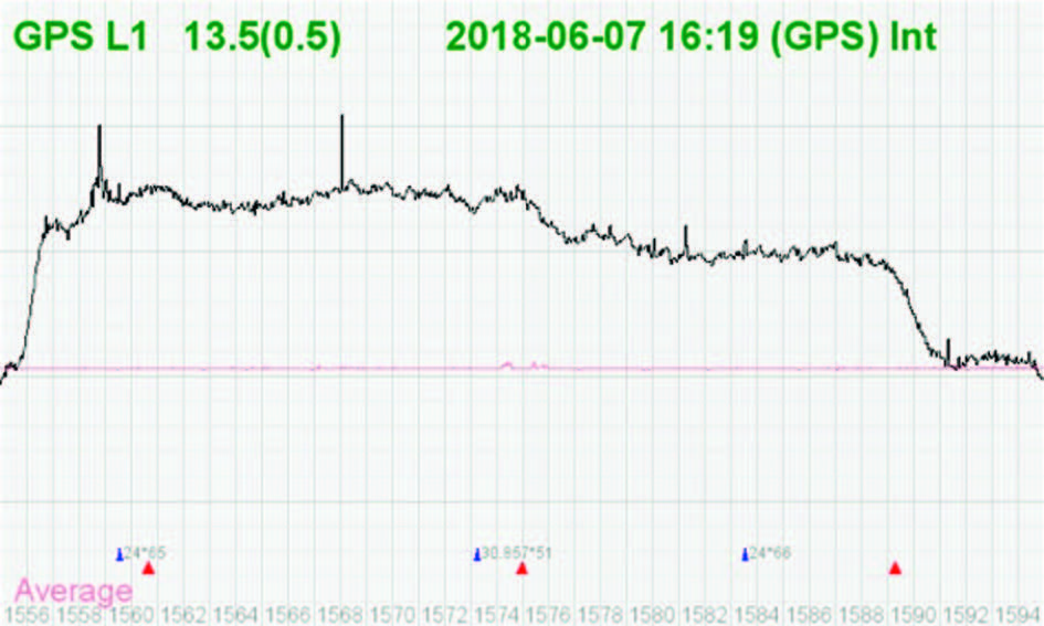
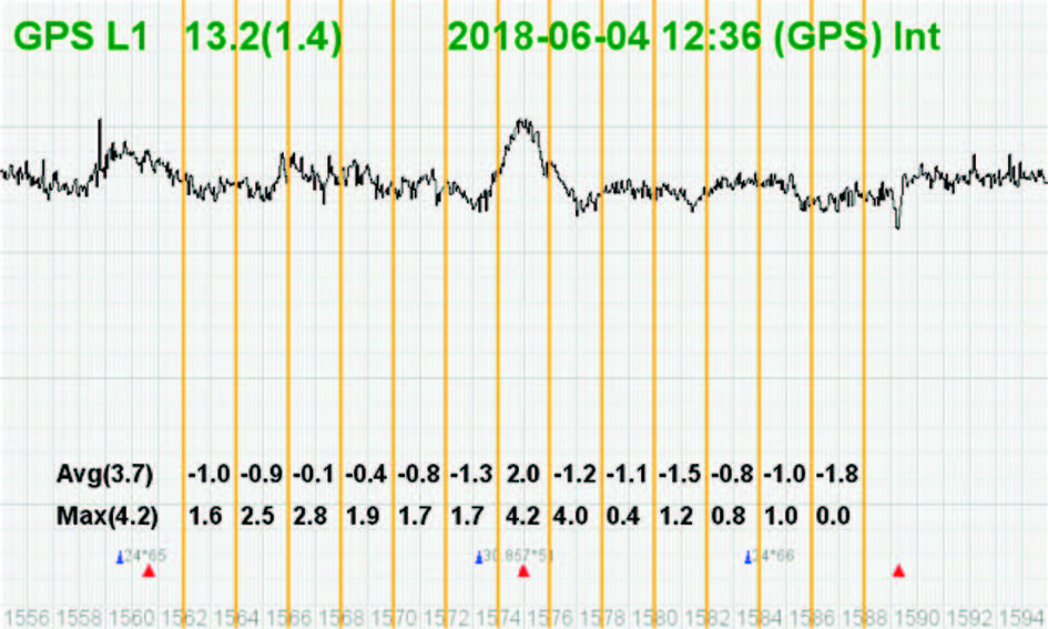
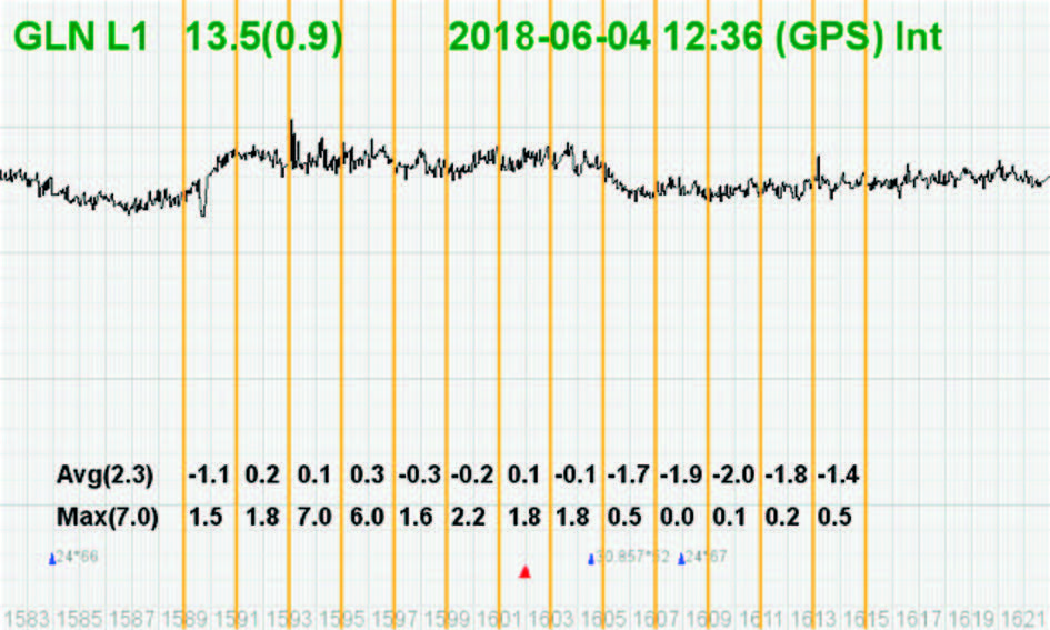
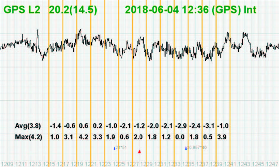
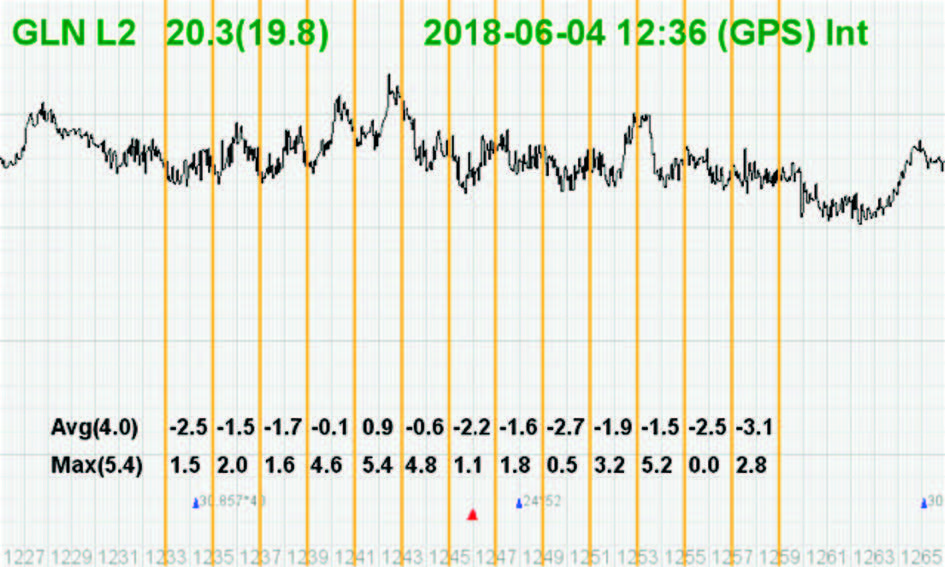
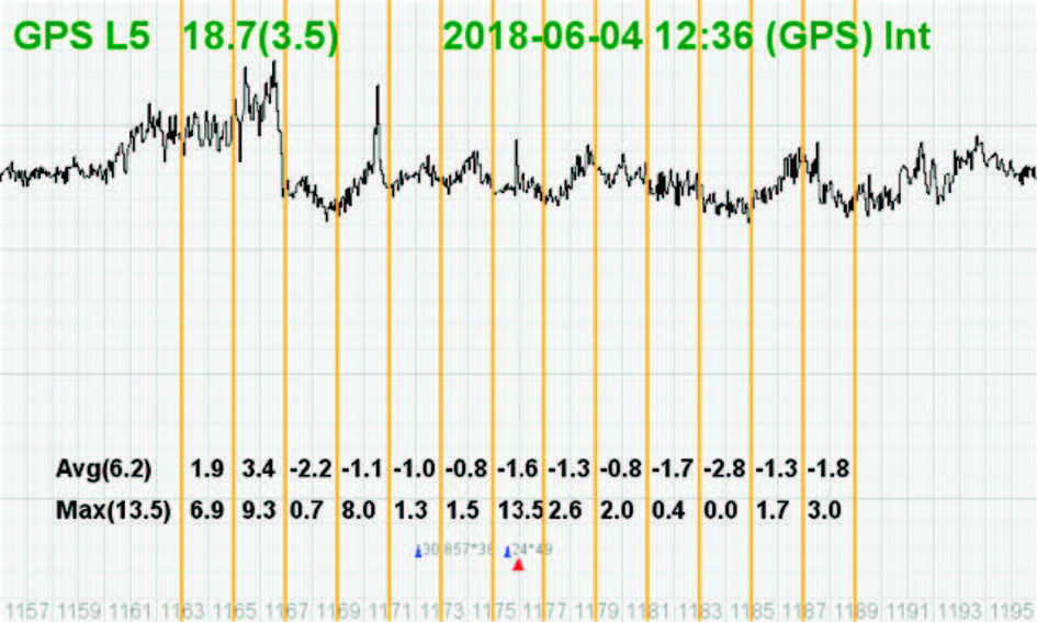
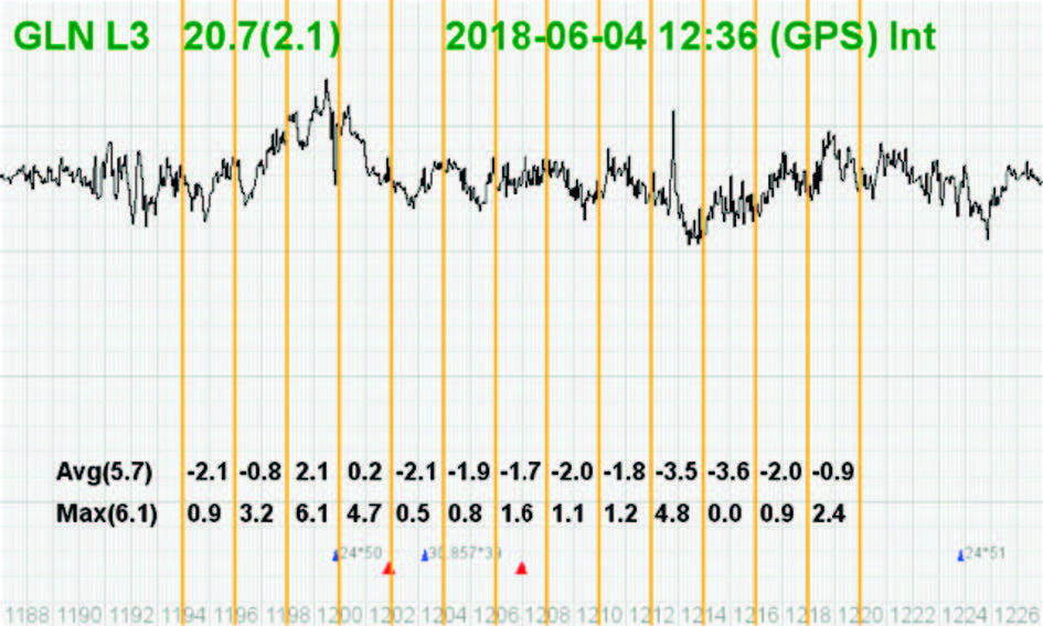
In addition to the spectrum, we also keep record of Automatic Gain Control which is another indicator of external signals.
The AGC monitors the environment and adjusts the gain to keep the voltage at a certain level. The change in AGC is an indicator of interference existence.
The narrow orange line in the middle of the band in this screenshot shows a quiet AGC.
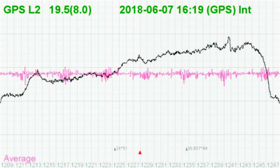
AGC in this screenshot shows there are activities in this band which our AGC was able to defend against it.
We believe it could be harmonics of GSM cellular phone near our site.
Our AGC mitigates the effect of such interference completely.
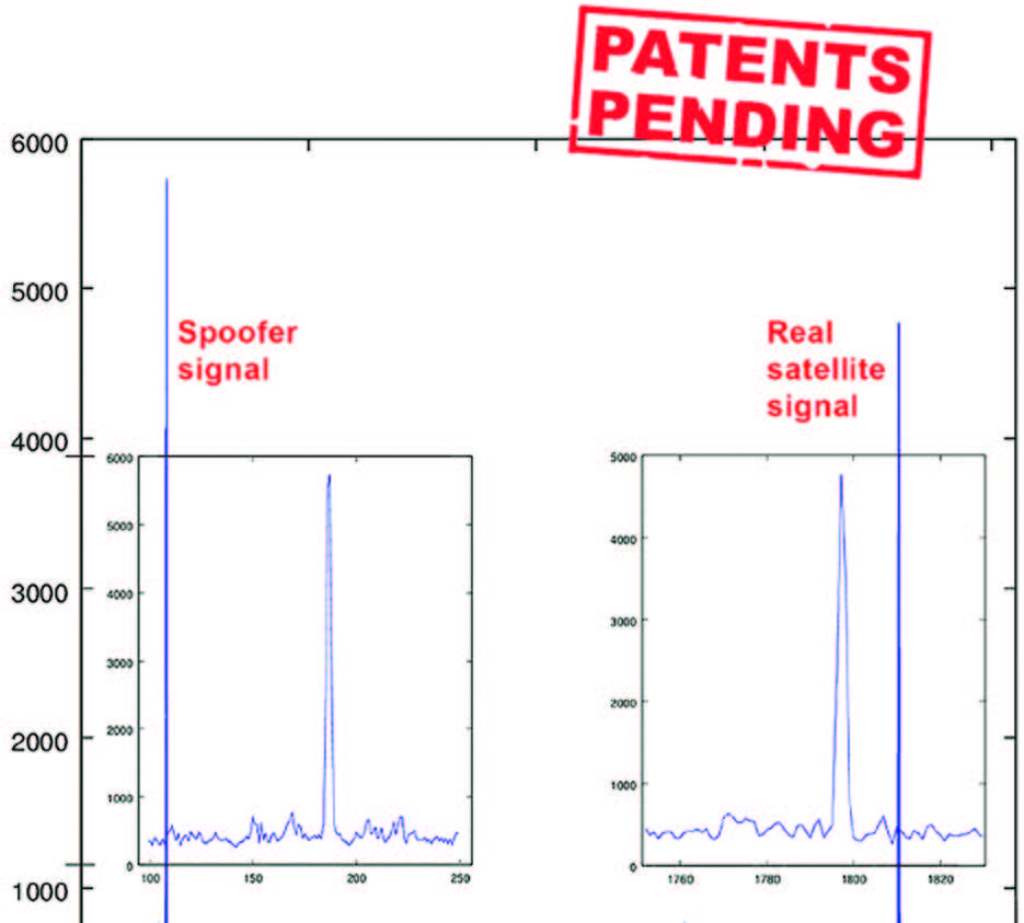
Spoofers & 2 Peaks
Spoofers are quite different from jammers. They don’t disturb the environment and the spectrum shape. They broadcast a GNSS-like signal to fool the GNSS receivers to calculate wrong positions.
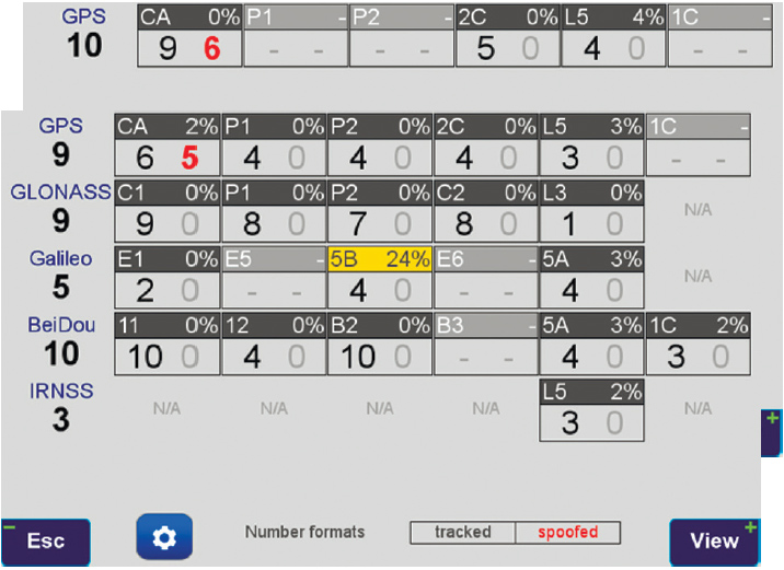
In the top screenshot 10 GPS satellites were visible (according to the Almanac). 6 of the 9 GPS satellites that we tracked were spoofed, as indicated by the red number, while the noise level was 0% in the GPS C/A band.
In the second screenshot, 5 of the 6 GPS C/A signals were spoofed while the noise in the band was only 2%.
We detect spoofers by digital signal processing. With 864 channels and about 130,000 Quick Acquisition Channels in our TRIUMPH chip, we have resources to assign more than one channel to each satellite to find ALL signals that are transmitted with that GNSS PRN code.
If we detect more than one reasonable and consistent correlation peak for any PRN code, we know that we are being spoofed and can identify the spoofer signals. Figure on the right is an example of two peaks. We isolate and ignore the wrong peak.
The screenshot on the right shows details of each signal. The first six lines in this screenshot show the spoofed signals that we detected as soon as they appeared (numbers “1” in those line). The two section columns represents the characteristics of each peak. Second SS column show if the second peak is a consistent signal.
While six satellites were spoofed, there was no indication on the noise level (0%) and no indication on the spectrum shape and level as shown on the screenshot on the right below the chart.
If the spoofer strategy is to cover the real satellite signal and then put the fake signal on top of it to produce only one peak, we notice that by more that 200% of noise level that it has to introduce.
We reject infected signals and then among all the available GPS, GLONASS, Galileo, BeiDou, IRNSS and QZSS multiple signals we use the healthy ones.
Usually there are over 100 signals available at any given time, and we need only four good signals to compute position. In rare cases that all signals are affected, we inform the user and guide them to use compass and altimeter to get out of the Jammed area.
There is absolutely no way that we can be spoofed without our knowledge. We will immediately recognize and take corrective action.
And Examples of when the world is peaceful.
Jamming and Spoofing protection option is available in all of our products and OEM Boards.
All screenshots are from our
TRIUMPH-LS Receiver.

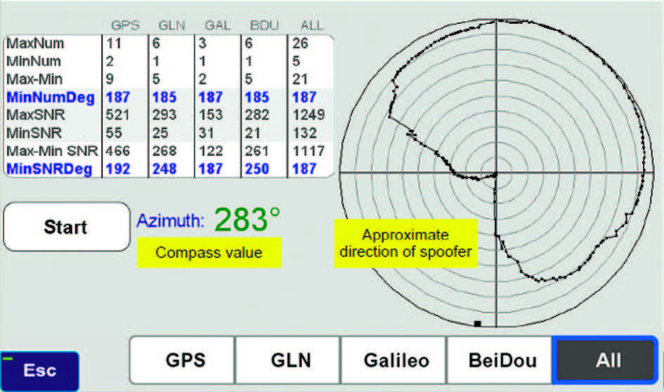
 When you detect that spoofers exist,
you can also try to find the direction that
the spoofing signals are coming from.
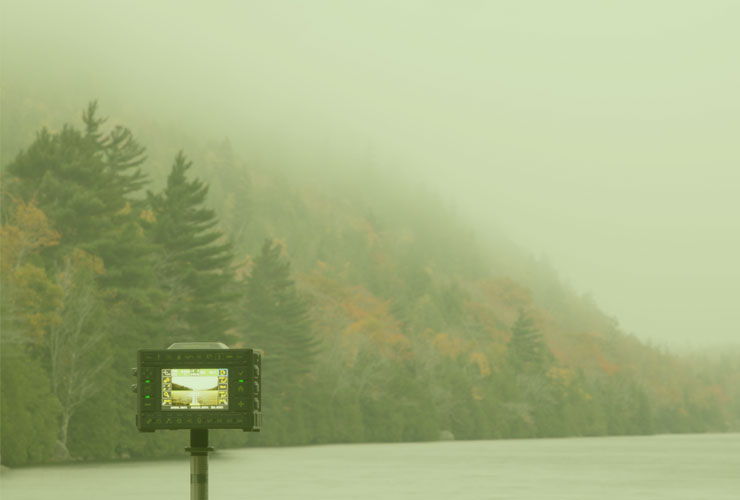
For this, hold your receiver antenna
(e.g. TRIUMPH-LS) horizontally and
rotate it slowly (one rotation about
30 seconds) as shown in the picture
and find the direction that the satellite
energies become minimum. This is the
orientation that the spoofer is behind the null point
of the antenna reception pattern.
When you detect that spoofers exist,
you can also try to find the direction that
the spoofing signals are coming from.
For this, hold your receiver antenna
(e.g. TRIUMPH-LS) horizontally and
rotate it slowly (one rotation about
30 seconds) as shown in the picture
and find the direction that the satellite
energies become minimum. This is the
orientation that the spoofer is behind the null point
of the antenna reception pattern.
After one or more full rotations observe the resulting graph that shows approximate orientation of the spoofer as shown in figure below.